Dome slaving – a recap
In the introduction to this series I described what slaving was and pointed out that the mathematics behind it is quite complicated. But worse, even when you have all the tools, it can be a bit of a minefield to get the system set up.
You have observatory control software (NINA, SGP, Voyager, etc.), a dome driver and sometimes an ASCOM hub ready and willing to do the maths for you. You need to decide which gets the job, so that the dome not only gets accurate instructions, but that it’s from only one source. Get this wrong and your dome starts doing all sorts of unpredictable things.
In this section we’ll discuss one option, setting up the observatory control program as the “source of all truth”.
Not only will it do the calculations, but it’ll also control the mount and dome directly through their relevant drivers. This is the simplest way to set up your observatory, and unless you have a good reason, this probably the way you want to do it.
Observatory control program as master
Automated observatories always have three components that are important to slaving:
- a dome
- a mount (with a telescope) and
- a computer
Of course, you’ll have other things as well, like cameras and autoguiders, but these aren’t important to slaving. At this point, you just need to concentrate on the way these three players interact.
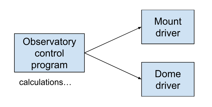
The most simple setup is to have the observatory control program as “master”. It can command the mount to slew to the target co-ordinates, perform the calculations for the required dome azimuth, and then command the dome to rotate to that azimuth.
For this scenario there are a couple of options, depending on how well your observatory control program communicates with your equipment. Ideally you can communicate directly, using ASCOM drivers or ASCOM-like communication programs like iOptron Commander or Pegasus Unity. We’ll talk about this direct connection method here, and move on to a less direct method in the next installment.
Observatory control program as master with direct connections
This is the scenario where you’ve got drivers that work well for both dome and mount, and you’re using them to connect directly. It’s nice and simple, and it’s our preferred way to run ScopeDome domes with iOptron mounts. The calculations are carried out by the observatory control program and the resulting azimuth is sent to the dome driver.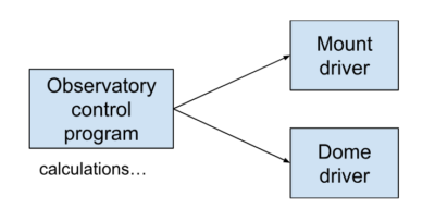
Mount setup (in Voyager)
Here we see that the observatory control program is connected directly to the mount driver. Specifically for Voyager, in Voyager’s Mount setup page, you select an ASCOM Telescope as the mount, and in the chooser, you select the ASCOM driver for your specific mount (in this case, ASCOM.iOptron2014.Telescope – this particular dome has a slightly older CEM60 as a mount). If you’re using some other dome automation software like NINA, there will be a different-but-similar screen to set it up this way.
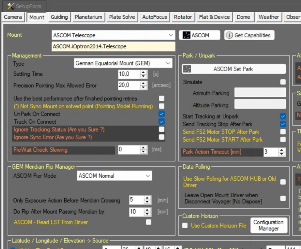
Note: if your mount has a direct driver rather than an ASCOM driver such as Green Swamp, EQMOD or similar, you would select that as the mount.
Dome setup (in Voyager)
If you have a ScopeDome, then Voyager can connect directly to the dome through its ASCOM driver. In Voyager’s dome setup page, you nominate an ASCOM dome, and then in the ASCOM chooser, select the ScopeDome driver from the list. It’s pretty simple. Other control programs will be very similar.
Calculations
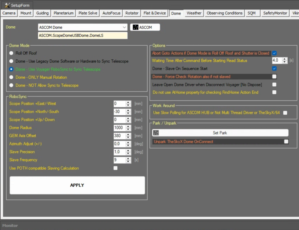
Remember that in this scenario, we’re having the observatory control software (Voyager) do the dome slaving calculations. To set this up, on Voyager’s dome setup page, select “Use Voyager RoboSync to sync telescope” (see the screen shot above). This will get Voyager to perform all the calculations for the dome slaving.
You will also have to enter the dome geometry parameters in the RoboSync section. This is the set of number that tell the observatory control software where your mount is in relation to the centre of the dome, how large your mount is, how large your dome is, etc. These numbers are crucial to the azimuth calculation, and you’ll have to measure those yourself. You can see our numbers on Voyager’s dome setup page in the screenshot above. (For example, you can see we’re in a 2M ScopeDome, because the radius is set to 1000mm.)
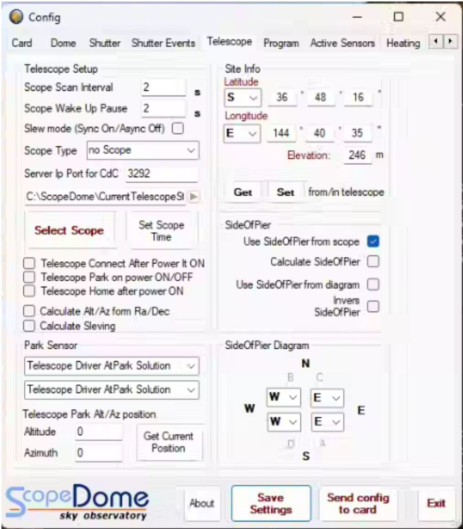
Important note: in this scenario, the dome control software is doing the slaving calculations. This means that in the ScopeDome driver, you must NOT have a telescope (remember that means “mount”) set up. That way the ScopeDome won’t be looking for instructions from any mounts. You can see this in the screenshot below where it says “no Scope” under “Scope Type”.
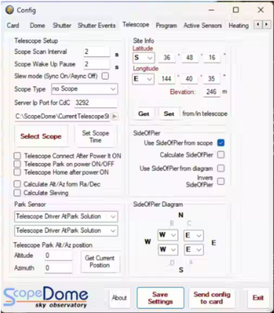
Incidentally, you can also use ASCOM POTH as a “no scope” equivalent, as long as there’s nothing actively connected to the hub.
Summing up…
With a process as complicated as this, you really want to do it the simplest way possible. That is, by having your observatory control program command both the dome and the mount, as well as being the sole performer of the required calculations. You really have to have a good reason not to do it this way.
The problem is, there are very often “good reasons”.
In the next installment I’ll go through what happens if one of your components (dome or mount, but others can stick an oar in) can’t communicate directly with your observatory control program.